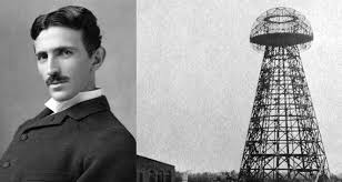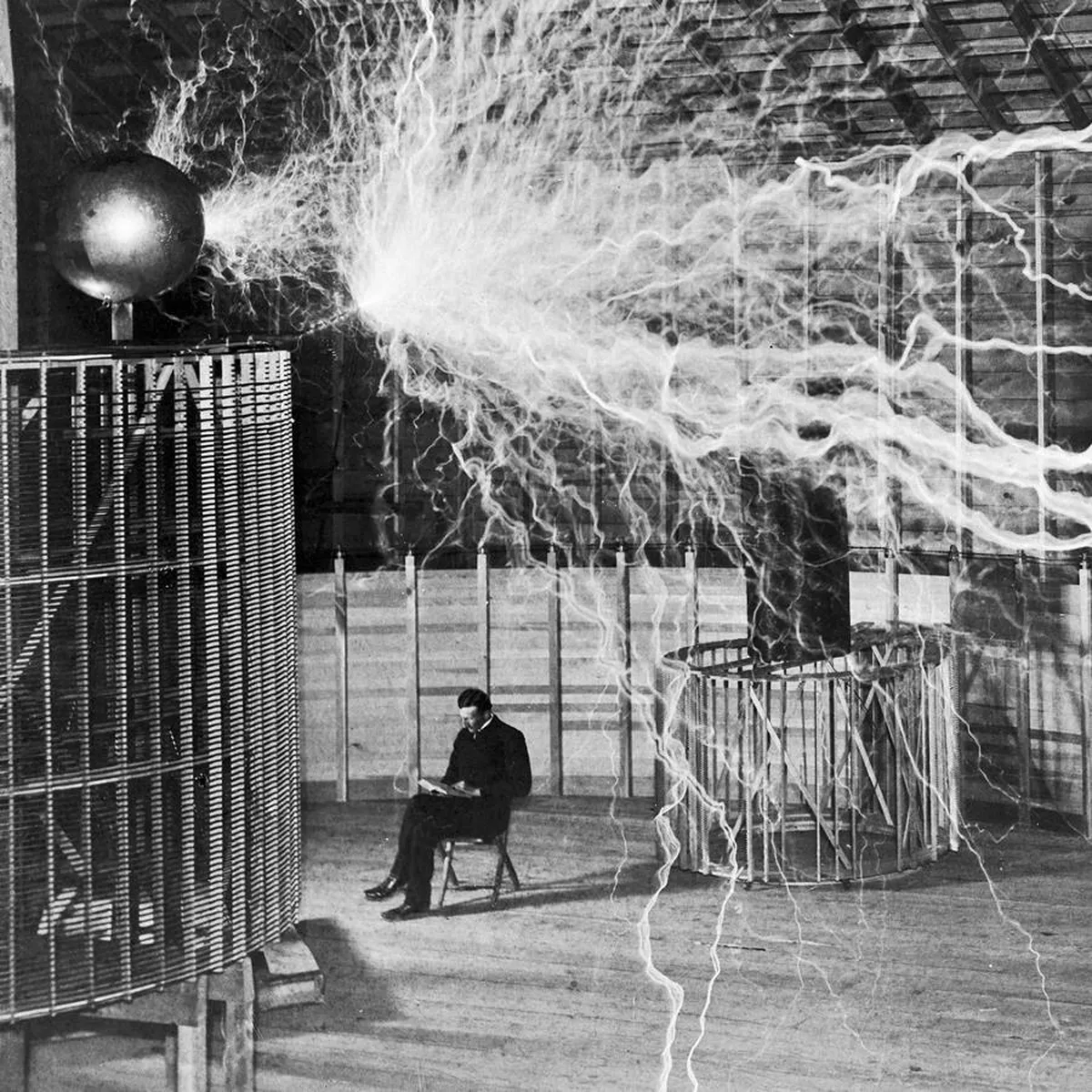


Nikola Tesla Secret — Complete Archive (with Bonuses)

Synopsis
The preserved Nikola Tesla Secret package — the book, the Tesla patents, and nine bonus guides — alongside salvaged copies of the Magnets 4 Energy and Bedini free-energy pages that have since vanished from the web.
The Complete Library
Nikola Tesla Secret — Complete Archive (with Bonuses)
A preserved copy of the Nikola Tesla Secret package — the original book, the Nikola Tesla patents, and the bonus guides — together with salvaged copies of the Magnets 4 Energy, Bedini, and free-energy pages that have since gone offline. Several of these sources no longer exist on the live web; what follows is reconstructed from local archives so the material isn't lost.
Reconstructed Sources
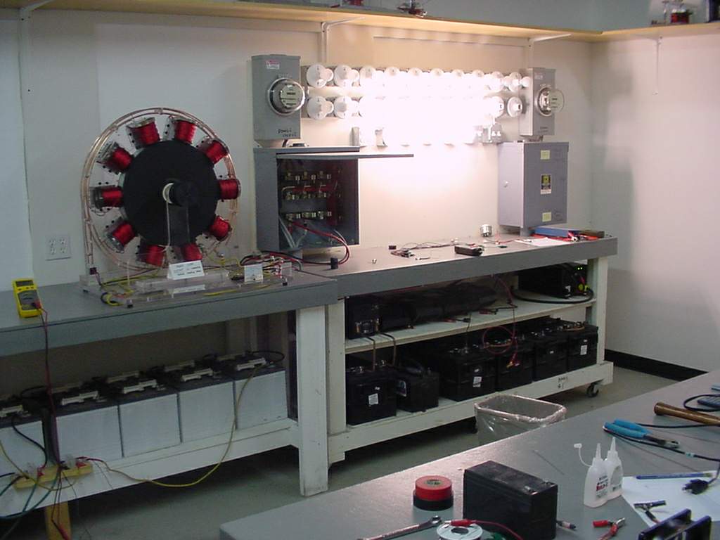
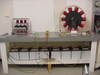
Bedini SG — Monopole Energizer

20 Bedini-Bearden Years
Free Energy Generation
Special thanks to all the groups
who kept the faith.
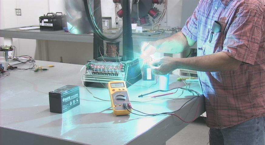
John Bedini discharging the radiant energy from the storage capacitors.
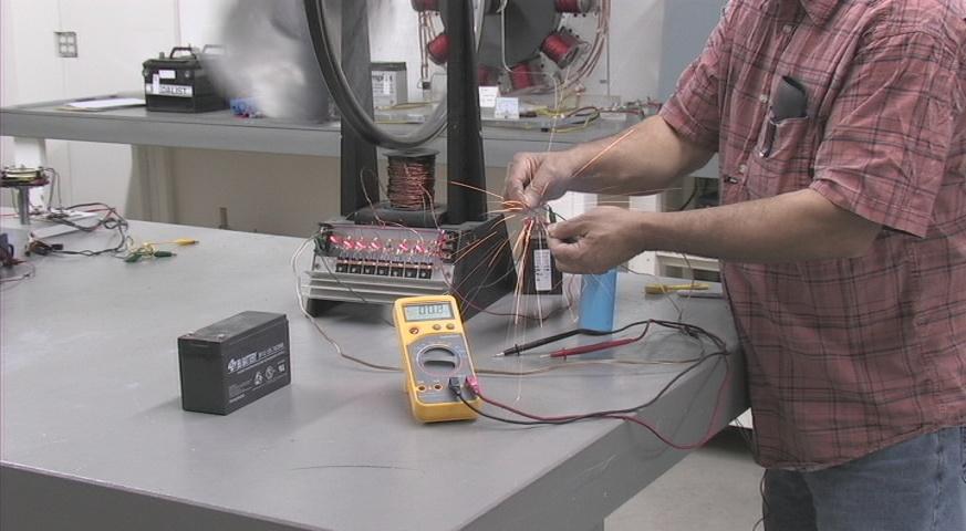
The current appears after the radiant discharge.

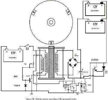
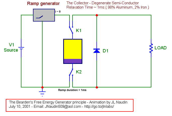
Tom Bearden 1984 Simple Free Energy Motor
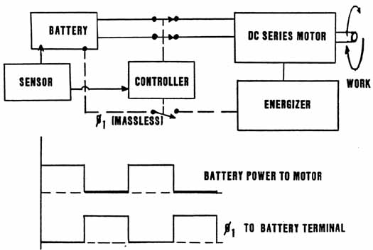
On this slide, we show a theoretical scheme which several researchers have discovered and used to build simple free energy motors.
In this scheme, we drive an ordinary d.c. series motor by a two wire system from an ordinary battery. The motor produces shaft horsepower, at -- say -- some 30 or 40 percent efficiency, compared to the power drained from the battery. This much of the circuit is perfectly ordinary.
The trick here is to get the battery to recharge itself, without furnishing normal power to it, or expending work from the external circuit in the process.
To do this, recall that a charged particle in a "hooking" del-phi river moves itself. This is true for an ion, as well as for an electron. We need only make the del-phi in correct fashion and synchronize it; specifically, we must not release the hose nozzles we utilize to produce our del-phi river or waves.
The inventors who have discovered this have used various variations, but here we show a common one.
First, we add an "energizer" (often referred to by various other names) to the circuit. This device makes the del-phi waves we will utilize, but does NOT make currents of electron masses. In other words, it makes pure Ø-dot. It takes a little work to do this, for the energizer circuit must pump a few charges now and then. So the energizer draws a little bit of power from the motor, but not very much.
Now we add a switching device, called a controller, which breaks up power to the motor in pulses. During one pulse, the battery is connected and furnishes power to the motor; during the succeeding pulse, the battery is disconnected completely from the motor and the output from the energizer is applied across the terminals of the battery.
If frequency content, spin-hole content, etc. are properly constructed by the energizer, then the ion movements in the battery reverse themselves, recharging the battery. Again, remember that these ions MOVE THEMSELVES during this recharge phase. Specifically, we are NOT furnishing ordinary current to the battery, and we are not doing work on it from the energizer.
If things are built properly, the battery can be made to more than recover its charge during this pulse cycle.
To prevent excess charge of the battery and overheating and destroying it, a sensor is added which senses the state of charge of the battery, and furnishes a feedback signal to the controller to regulate the length of recharge time per "power off" pulse. In other words, the system is now self-regulating.
The relation between power pulses and recharge pulses is shown on the graphs at the bottom. Note that regulation may decrease the time of recharge application of the del-phi river.
This system, if properly built and tuned, will furnish "free shaft energy" continually, without violating conservation of anenergy. Remember that the del-phi condition across the battery terminals means that spacetime is suddenly curved there, and conservation of energy need no longer apply.
Again, this system is consistent with general relativity and with the fact that Ø-field alone can drive a situation relativistic. We have deliberately used these facts to do direct engineering. Our "extra energy" comes from shifting phi-flux **-- *the energy of the universal vacuum spacetime -- directly into ordinary energy for our use. Thus we draw on an inexhaustible source, and our device is no more esoteric than a paddlewheel in a *river. The only difference is that, in this case, we have to be clever enough to make and divert the river in the right timing sequency.
This is a free energy device which an ordinary person, who knows a little electronics, can experiment with in the basement. To develop it, one is talking several thousands of dollars and a lot of persistence and tinkering; one is not talking millions.
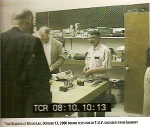
Tom Bearden and John Bedini testing a monopole energizer
Tom Bearden John Bedini during a TUV test
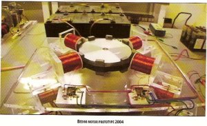
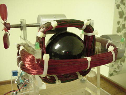
Dual monopole motor Test
Dual monopole
Testing of the Bedini Cole circuit , The Real McCoy
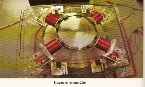
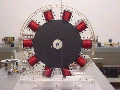
4 Pole Monopole motor
4 Pole Monopole motor
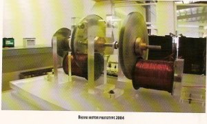
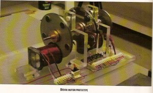
Bedini Motor Generator first patent
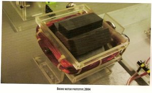
Bedini Motor Generator first patent , charging batteries
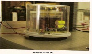
Bedini Cole Window Motor
Test Bedini/Cole Motor no battery.
http://www.johnbedini.net/john34/bedinicolemotor.mpg
Window Motor, Bedini/Cole This motor has been on the same batteries for over 15 years.
http://www.johnbedini.net/john34/Window.wmv
Tom Beardens web sight
http://www.energyfromthevacuum.com/
* *
Energy from the Vacuum
A Documentary Series
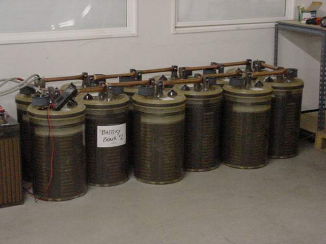
The biggest monopole motor charging 1800 amp hour batteries over 300 pounds each cell.
 *
*
*Running load bank 2000 watts for 10 hours continuos
Book reviews
A wonderful book indeed! As one who has succussfully replicated many of these machines in many variations, I can say that this book is very helpful to understanding this technology. The very lengthy patent quoted shows many important things not shown to the public until now. The explinations are the clearest I have seen yet, and are very well developed. Several new circuits are shown, as well as several methods of tapping into the Aether. We have shown the public on several of these forums how you can see the over unity in the results. The benefits of this technology are really incredible. The environmental benefits are enormous. I have been able to not only restore junked batteries to useable and better condition, but also can even recharge non-recharageable batteries with the circuits shown in this book. Further, I have been able to charge several batteries with only one equally size and charged battery powering the the front end. This, as I have shown, can be done by properly tuning the setup with more than one battery on the back end, or by placing Energizer coils on the freely running wheel and charging up additional batteries or loads, or even the front end load. This I have done numerous times over the last two years. This was shown in the original 1984 book, which is given at the start of this book. This is very easy for anyone to see for themselves as many have. All you have to do is make the machine so that it ends up charging the charging battery to even only 90% of the rate of discharge of the primary. If you then can charge up another battery with an energizer off the freely spinning rotor, then what do you have if even that is only 90% of the charge and the primary is discharged? Anyone should be able to get at least these low results. And what does that show you? But with a little more quality and effort you should be able to get one fully charged battery for one fully discharged battery, with a free mechanical load that can power whatever you want, or another battery. With the slightly advanced motor as shown on the lists long ago, you can swap the batteries around and continually get this free ride or extra charge. You must add in the free mechanical. Remember, the SSG setup was the bare bones basics to show you something. This book goes further into the meat of the matter. The book has many illustrations and color pictures. For those who were pressing for more details, here they are. Enjoy!
Rick Friedrich
12/03/06
This book gets an A+++++!! I've had this book for a week now and haven't been able to put it down yet.Tom Bearden and John Bedini really nail it in this one! On page 46 of this book, it has John's solidstate version of his monopole! complete with component values! Now people don't have any excuses why they can't build this because you no longer have to build a rotor! I've been replicating and testing Bedini's energizers for three years now, and was an original member of Sterlings Yahoo SG group. I've seen some amazing results with my projects, but nothing like what I'm seeing now that I've built the solidstate version that is in this book! I've recharged alkaline batteries without heating them (That I've seen before). I got a 1 to 1 charge by using a 12volt 17aH battery to charge a 12v 250 aH battery! and, the best thing yet, I hooked this Radiant energizer up to a water capacitor(electrolysis chamber) that was filled with sodium free spring water with NO electrolytes and imagine my surprise when gas started streaming off the plates with only 200mA of input! and after running it at about 1 amp 20v for just over 20 min, the water was still cold! I have never seen anything like this and I've experimented with straight DC and pulsed DC looking for that (now) fictional resonant freq of water. To be fair though, there are some problems in this book.There are some minor typos in the back artical,the opto pin outs have the emitter and collecter pins backwards, and their is a NPN in one of the schematics with a PNP part number.Just minor stuff a little common sense can over come. This book is truly historic and is going to blow the mind of any one open minded enough to read, consider, and experiment. I have no doubts that John and Tom are real from what I've seen on my bench and from what I have read in their works. Is there any surprise there is a campaign to discredit them? I'm not. This whole oil business thing is fishy. Are we really to believe some oil company is so smart to make up all the details of Tom's theories and related machines, but are so stupid that they leave an obvious connection to themselves? The whole supposed oil companies site looks like some half ass web template, like someone put it up with Tony's address and phone number in order to discredit Bearden. How hard is it to get a number listed in a business directory anyhow? Even if Tony is some oil tycoon, isn't it possible Bearden doesn't know and is being manipulated to some degree? I don't know, but then you have this Eric Kreig guy who was personaly mentored by someone who likes to 'debunk' with slight of hand tricks, "The Amazing Randi". These super skeptics are just as bad as super gullible people. If critical thinking was explosive, these clowns wouldn't have enough to blow their hats off. Just keepers of the status quo if you ask me. I would suggest buying this book before it's stopped! It's that powerful!
Dave AKA Oneness
P.S. Eric Kreig, I sure hope your working on your public apology to Tom and John, the truth is now out and it's only a matter of time before everyone knows who is for real ;)
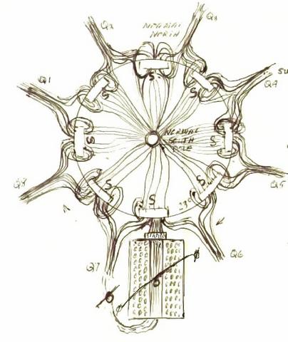
The way I see the magnetic fields around the monopole system
Circuit diagram of the monopole motor
12 Pole Monopole running
http://www.johnbedini.net/john34/Mono-Pole.mpeg
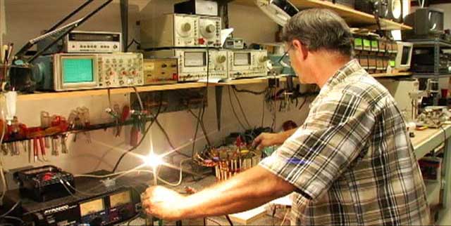
John Bedini running a solid state radiant amplifier oscillator, Hendershot design
Books from Tom Bearden
http://cheniere.org/books/FEG/index.html
- The Attractions of Magnetism.
- Could a Little Child be Leading Us into a Free Energy Future?
- **By Jeane Manning. Atlantis Rising, November 200(?), pg. 32..
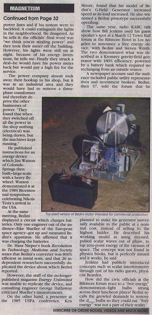
- The search for new energy technology takes us to northern Idaho to meet a ten-year-old girl who won a science fair with a battery-charging motor. She describes it as an advanced design that extends the life of* batteries for an amazing length of *time. The motor was designed by John Bedini and built by her. We meet him first.
- More widely known as an audio-amplifiers expert, Bedini's name is intertwined with 'free energy' history. Witnesses saw his machines running successfully, but later others were unable to build devices according to his published instructions. His circuitry was mentioned favorably at a conference in Switzerland recently.
- Aware of* *the controversies, with mixed feelings I drove into the Idaho panhandle, past a warehouse for survivalists' supplies. My hope is that he will give clues so others can duplicate his successes.
- Explaining his theory about such devices, new-energy theorist Thomas Bearden is writing prolifically this year. Retired from electronic warfare studies and aerospace work, Bearden is the leading advocate of scalar potential electromagnetics, and he explains how the sea of energy we live inan energetic flux of virtual particlescould be engineered to do work in the physical world.
- Bearden also has a theory about another of Bedini's 'scalar' inventions--one which can increase enjoyment of music. After a six-year struggle, Bedini was granted US Patent 5,487,057 for a mechanism for reducing electronic distortion in digital and analog recording and playback. Bearden (writing in *Explore Magazine Vol. *7, No. 4. pp. 53-63) says the patent examiner couldn't understand the mechanism, because Bedini's nonlinear optics process was not found in audio or classical electromagnetics textbooks. Meanwhile, John and his brother Gary were already selling the stress-defect-relieving devices. The process even works for media such as color film. Bearden explains Bedini's process as self-oscillating, optical electronics, and hopes that even standard metals can eventually be treated with it to reduce stress defects. Is this negative entropy--self-ordering in the physical world?
- Bearden adds that most really now things are invented not by academic teams or corporate scientists but by the lone "independent fiercely creative people."
- I meet Bedini at his business, surrounded by electronics equipment. The back room looks like a museum of small prototypes of unusual motor/generators. Some are pictured on websites http://rand.nidlink.com/John1 or http://johnbedini.net/john1/tesla.html
- He says his knowledge is on the Internet, and now it's up to others to build the devices. He says they have to experiment themselves, and it reminds me that he taught a little girl how to make a motor which drove science teachers nutsto see a little motor made of plastic with no return paths for the magnetics.
- "The funny thing was that her father bent a coat hanger and put a coil above the motor and used it as a generator. The motor ran much longer under the load than they had expected."
- John Bedini was roaming the "free energy" scene in California in the 1970s and early 1980s, collecting knowledge about medical as well as energy devices. He had an electronics business in Sylmar, and at home he experimented with windmills and other systems. The utility company objectedhe was hooked up to their power lines and if his system were to backfeed, it could extinguish the lights in the neighborhood. He disagreed. As he tells it, the officials' final word was "we think you're stealing power" and they took their meter off the building. However, his lights were still on at night, because of his energy inventions, he tells me. Finally they struck a dealhe would have his power meter back but would pay a high fee for the service.
- The power company almost took away their hookup to his shop, but it was in an industrial area and they would have had to remove a three-phase transformer and therefore deprive the other businesses of power. "They found that when they switched off all the power in the shop nothing (electrical) was being drawn, but the machines kept running."
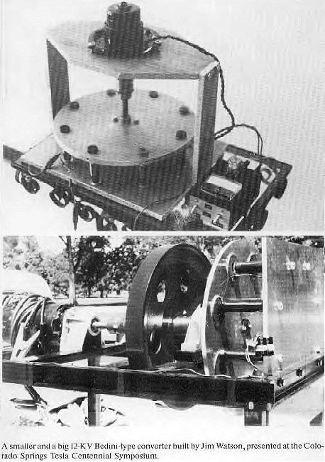
- He published instructions for an energy device which Jim Watson of Colorado Springs then builtlarge-scale with a heavy flywheel. Watson demonstrated it at the 1984 Bicentennial symposium celebrating Nikola Tesla's arrival in the USA.
- At the same meeting Bedini displayed a circuit which charges batteries. Only one engineer out of the audienceEike Mueller of the European space agencygot up and measured Bedini's apparatus. He affirmed that it was charging the batteries.
- Dr. Hans Nieper's book *Revolution in Technology, Medicine and Society *states that Bedini's convener was 800% efficient in initial tests, and that 26 independent researchers successfully duplicated the device about which Bedini reported.
- However, the staff of the no-longer-published magazine *Energy Unlimited *was unable to replicate the device, and consulting engineer George Hathaway criticized Mueller's measurements.
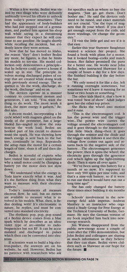
- On the other hand, a presenter at the 1985 USDA conference, Ken Moore found that his model of Bedini's G-Field Generator increased speed as its load increased. He also witnessed a Bedini prototype successfully operating.
- The same year, radio KABC talk show host Bill Jenkins used his guest speaker's spot at a March 12 Town Hall forum at the Biltmore Hotel in Los Angeles to announce a free energy device, with Bedini and Steven Werth. The two demonstrated what was described as a Kromrey gravity-field generator with 180% efficiency, powered by a battery bank which required no recharging from an outside source.
- A newspaper account said the audience included public utility representatives and investment brokers. Bedini, then 37, told the forum that he planned to make his generator universally available to the public at a nominal cost, instead of selling to the highest bidder. He described his working model as using stressed pulsed scalar waves out of phase, to tap zero-point energy of the vacuum of space. The concept was not found in physics books, but is perfectly natural and it works, he said.
- Jenkins had publicly introduced concepts such as scalar interferometry through one of his radio guests, physicist Bearden.
- How did the civic officials at the Biltmore forum react to a "free energy demonstrationlight bulbs strung across their luncheon plates? Bedini recalls they growled demands to remove the dam bulbs so they could eat. "Free energy" was not a part of their reality.
- Within a few weeks, Bedini was visited by two thugs who were definitely unfriendly toward his efforts to unhook from today's power structures. They had the appearance of body-builders who had just stepped out of a gymnasium, and pushed him against his shop wall while saying in a threatening manner that they expect he will continue to use gasoline. He laughs shortly while recalling the incident, but evidently knew they were serious.
- Now that he has moved to Idaho, the reason "they" don't bother Bedini any more, he figures, is that he limits his models to toy-size. His model collection only demonstrates a principlethat he believes could power a house if scaled up in size. The principle involves storing discharged pulses of energy that are created while doing work with previously stored energy. The sequence is "do the work, discharge, do the work, discharge" and so on.
- The devices operate in a manner contrary to conventional motors and generators, I am told. "You want the thing to do work. The more work it does, the more energy it gathers: Bedini says.
- A recent model, incorporating a bicycle wheel with magnets glued on the inside of* *the perimeter, has a large-bladed fanangled to slow the rotation--as the work load. Bedini unhooked part of his circuit to demonstrate the spark. He was showing how much energy is sent back to the battery, continually in step. Repeatedly the setup runs the motor for a certain length of time, shuts it off and then discharges.
- Bedini is scornful of experts who have visited him and can't understand why a small motor could be charging a battery yet the motor does not slow down.
- "We understand what the energy is. Tesla knew exactly what it was. And it's the furthest thing from what they want to measure with their electron pushers."
- Today's instruments all measure electron flow, he said, but no meters are available to measure what is involved in his models. What, then, is Bedini dealing with? It's electrostatic in nature, he replies, and must be converted into standard electricity.
- The rhythmic pop, pop, pop sound of a Bedini device comes from a blue spark which he describes as an ultra-violet type of arc-similar to radio-frequencies but not RF. It can be accumulated and discharged in pulses which then can be converted into electrons.
- If* *scientists want to build a big electron-pusher, the answers are on his website, he said. However, Bedini has no patience with researchers who ask for specifics such as where to buy the magnets. "Just go get them. Don't bother me." He said the devices only need to be tuned, and exact materials are not crucial. "Use the type of magnets that fit your wheel. If you don't get enough output from the coils, and more windings. Or change the geometry."
- I'll visit the little girl and see if it is that easy.
- Earlier this year Shawnee Baughman wanted a science fair project. She found a book with plans for a motor, but it looked boringcorks and match boxes. Her father promised the parts for a better one. He works near John Bedini, who instructed Shawnee for a couple of hours a day for a few days. She finished building it the day before the fair.
- "We only tested it for like a day, left it running overnight sometimes, but sometimes we'd leave it running for an hour or two hours or something."
- The other kids liked it; that's how it was voted 'best of show'. Adult judges gave her the other top prizes.
- She flicks the wheel, into motion and it runs.
- "This is the electromagnet coil. It has the power wire and the trigger wire... The power wire carries the voltage around the electromagnet coil and it goes through to the transistorthat little black thingthen it goes through the resistor and the diode and the trigger wire follows it and then the voltage flow comes out again and returns back to the negative side of the battery... The electromagnet generates the power, then it spins the wheel; the electricity goes through the generator coil which lights up the light-emitting diode. Then it starts all over again."
- "We've been using this battery for a month or so now. It's supposed to have only 900 spins per nine volts, and that's a nine-volt battery, so if it were to run out then it would have run out a long time ago!"
- She has only changed the battery three times since building it six months ago.
- Schools' involvement in the new energy field adds impetus. Andreas Manthey is an instructor who organized a Study Group for Free Energy at the Technical University of Berlin, Germany. He says the German version of my book impelled him back into new-energy research.
- Jim Watson disappeared from the public new-energy scene a couple of years after the 1984 demonstration, but John Bedini and colleagues are sharing as much information as they believe that they can share. Bedini views children such as Shawnee as our hope for the future.
- This proves that the energy can be stored in a capacitor then discharged to the secondary battery.
- To see a school girl motor running and discharging into a light bulb, built by the real Harlen Sanders.
- Go to johnbedini.net/john34/BediniMotor.wmv
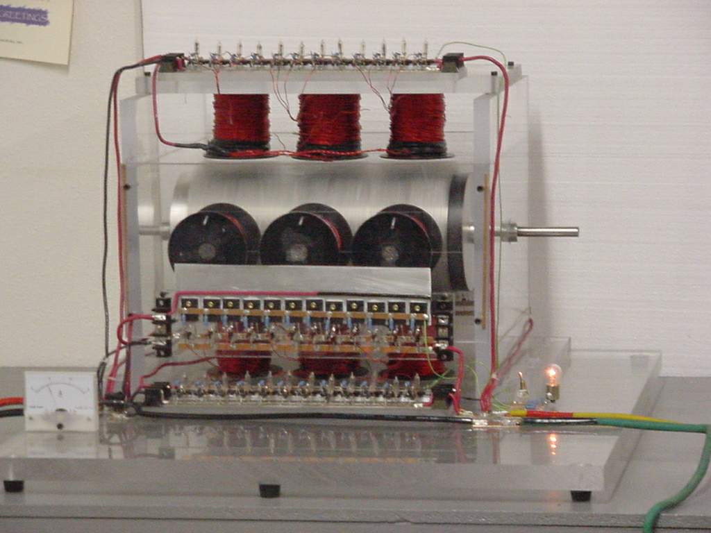
The SG project building a six coil machine
johnbedini.net/john34/kron.html
TUV Test
**
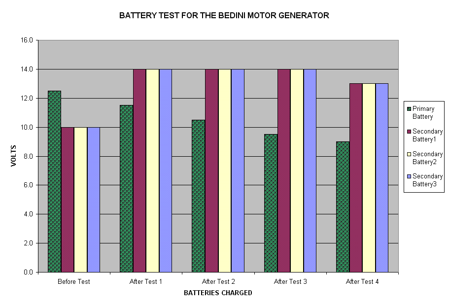
BATTERY TEST FOR THE BEDINI MOTOR GENERATOR**
DATE : OCTOBER 13, 2000
BATTERY TEST SEQUENCE:
One lead acid gel-cell (12 volts, 450 milliamps) is being utilized as the primary source fully charged at 12.5 volts
Three (3) lead acid gel-cell batteries (12 volt, 450 milliamps) strapped in parallel are being used as the charge destination. The batteries are discharged to 10 volts for the test purposes.
Test #1 starts at 10:45 AM utilizing primary battery fully charged at 12.5 volts charging three (3) destination batteries paralleled. The destination batteries reach a charge capacity of 14 volts at 11:20 AM.
The destination batteries are then discharged to 10 volts under working load to prepare for Test #2.
Test #2 starts at 11:25 AM utilizing primary battery measured at 11.5 volts. Charging three (3) destination batteries paralleled. The destination batteries reach a charge capacity of 14 volts at 12:50 PM.
The destination batteries are then discharged to 10 volts under working load to prepare for Test #3.
Test #3 starts at 1:00 PM utilizing primary battery measured at 10.5 volts. Charging three (3) destination batteries paralleled. The destination batteries reach a charge capacity of 14 volts at 1:40 PM.
The destination batteries are then discharged to 10 volts under working load to prepare for Test #4.
Test #4 starts at 2:05 PM utilizing primary battery measured at 9.5 volts. Charging three (3) destination batteries paralleled. The destination batteries reach a charge capacity of 13 volts at 2:40 PM. The primary battery is now discharged to 9 volts under working load and unable to further run the
**
TOTAL BATTERIES CHARGED:
**
12 lead acid gel-cell batteries (12 volts, 450 milliamps each). This ratio is a 12 to 1 charging factor. The motor operation (work) being performed as this was done is not included as an additional factor in this test.
** **
Ok, done!
Source (preserved): 20 Bedini.html
Free Energy Magnetic Generator
See New Mini-Romag Data – click here
Mini-Romag Generator****
DRAWINGS:
** Mini-Romag Generator (PDF 260KB)**
** Mini-Romag Generator CAD cut-away (.dwg 704KB)**
** Mini-Romag Generator CAD Rotor (.dwg 186KB)**
** Mini-Romag Generator CAD (.dwg 781KB)**
- **Generator runs on free energy provided by magnets and the earth's energy field **
- **Generator produces magnetic current equivalent of 3-1/2 volts and 7 amps **
- **Generator requires startup of 2100 RPM for 42 seconds **
- **Suggested use for generator: charging magnetic battery, powering small magnetic devices like a magnetic water pump **
- **Generator does not produce pollution **
- **Generator is designed to recycle magnetic energy back to help save environment **
- **Materials necessary to construct generator are readily available **
- Generator requires a load to maintain continuous operation ****
We are providing this free information out of love to help save our planet. Please help us in educating people about magnetic energy.
ABSTRACT
This generator is a magnetic device incorporating the use of permanent magnets turning with a rotor to generate a magnetic energy which is then circuited to other mechanisms to do useful work. This mini generator demonstrates that magnetic principles can be utilized in units of various sizes. Magnetic units can be microscopic or a mile wide, as long as the correct principles are maintained. When magnetic fields are properly harnessed, when the magnets and housing are a certain composition, when the magnets are rotating at the proper rpm, and when the energy is given a redistribution path, a very powerful phenomenon occurs; the natural flow of Universal magnetic energy begins to escalate. All magnets draw energy in to maintain their power, but under the right conditions magnets can assist in attracting large quantities of magnetic energy that can be used for numerous purposes.
**It is critical to remember that this magnetic generator does not create pollution while it is running. The conventional processes used to obtain the materials obviously create pollution, but as people progress beyond the current destructive technology, even the processes of extracting natural resources and manufacturing materials will become less polluting. It is also critical to note that this device is designed to recycle the energy it uses from the Earth's energy system. Scientists will soon come to a consensus that electricity does not properly harness the natural flow of energy and that the electrical power system does not properly recycle energy after it is used. The environment is suffering because of current technology, especially electricity, and it is becoming critical that people begin to switch to a new form of energy production. **
Many of the negative effects of electricity production are apparent to most people, the stripping of natural resources and the millions of tons of pollution that power plants pump into the atmosphere. But the Earth's system is being severely affected by critical energy interaction that is occurring between electrical fields and the magnetic field around the planet. The focal point of electricity's negative effect on the environment occurs in the ionosphere. The ionosphere is a sea of pulsing neutrons that assists in sustaining life on this planet. The ionosphere supplies the energy for any system in the environment that requires energy to function. Power planets are constantly drawing energy from the ionosphere to maintain functioning. The problem is the power plants do not use the energy properly, nor do they recycle the energy back to the ionosphere. Running power plants create an imbalance in the Earth's energy field that causes the ionosphere to perform a rebalancing process. Powerful vortex fields form in the ionosphere that draw energy up to restore the depleted field. These vortex fields often result in dangerous storms that involve tornadoes and hurricanes. The H.A.A.R.P. Project (High-frequency Active Auroral Research Project) in Alaska is a multi-billion dollar governmental project that researches the interaction between electricity, the ionosphere, and the weather. See Dr. Nick Begich's book Angels Don't Play This HAARP to learn more about this project.
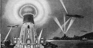
Nikola Tesla had a firm understanding of the interaction the ionosphere had with energy systems. Tesla designed many devices that form the foundation of today's technology. Tesla also invented magnetically based devices that were never produced in large quantities that were far superior than today's technology. Through his research on magnetism and electricity, Telsa repeatedly demonstrated how intricately the energy fields we generate are connected to the ionosphere. Telsa also proved over and over that weather can be influenced by artificially generated energy fields. For decades, the government has been using Tesla's concepts to test and abuse the ionosphere without regard for the environment and the safety of people.
It is critical that people stop damaging the ionosphere with electricity, not only because the weather will become increasingly severe, but because ozone holes are continuing to form and expand. Chemicals have never been the cause of the ozone holes. Electricity production is the primary cause of the ozone holes, and many scientists have known this for many years. It is an electrical interaction that is altering magnetic molecular structures preventing a natural restoration to the planet's energy field that is creating the ozone holes. The process forming the ozone holes will be stopped because without the ozone layer, life will cease to exist on this planet.
The time will come in the near future when the Earth will undertake a pole shift that will alter the magnetic field around the planet. This pole shift will make electricity generation impossible. The ionosphere will no longer supply the energy structures that make it possible for power plants to generate electricity. This pole shift will force people to use different technology, like magnetic energy, to power devices. The revelation of a pole shift and the changing magnetic field is being given to many people, and it is a necessary process for the Earth to undergo to begin the process of healing, or rebuilding the energy field around it to ensure a stable, long lasting system. Magnetic technology will assist in rebuilding the system and ensuring our long term survival.
PRINCIPLE BEHIND THIS ENERGY SOURCE
This generator utilizes neutral magnetic energy from the Earth's energy field by attracting the energy through the proper magnetic harmonic. The unit captures the energy and changes it into a polarity that magnetic devices can accept. This simple unit is like a water wheel, it only functions if a flow is moving through it, and it will continue turning as long as it is being used to power something.
An important object of the present device is to provide a revolutionary new concept concerning the utilization of power by directly capitalizing on the natural resource of magnetism. Electrical power is the result of expending energy to drive a copper wire through a magnetic field. But magnetic energy is a natural resource needing a specific mechanism to draw on. There is no incorporation of a secondary energy source except at start-up, to cause this magnetic generator to continuously function.
HOW THE UNIT FUNCTIONS:
The here disclosed 31/2 volt, 7 amperage magnet motor/generator must be charged up by driving the main shaft at 2100 RPM for 42 seconds. This charging process manifests as magnetic energy within the six coils of copper wire, the copper tube supporting these coils and the copper coated steel wires wrapped around the magnets. This charging is accomplished while the six coil connection wires, Part #22, are making contact and setting up their alternating magnetic poles. After the 42 second charging time one of these coil connection wires must be opened and this circuit again completed through an energy draw at what could be called 7 amps. See load Part #23. As current is drawn from the six coils, this draw sets up magnetic poles which are a response between the rotor magnets and the coils. This response then causes the main shaft to be rotated by the 12 permanent magnets as they attract and build a release field. Then the driver unit (hand crank) is disconnected allowing the unit to rotate with the load being the activating driving force.
The fields of the magnets must be maintained during their spin movement. These magnetic fields which are encapsulated are achieved by the wiring system. The attract/release of the magnets is a function of several factors. First, the magnets attract field between north and south is completed by taking a crossing path of attract (top of one row to bottom of next, etc.). This action has the effect of fields blending into fields, and a hold-back attract does not happen. Each time a magnet set passes a coil an interchange of like energy between the coils around the magnets and the generating coils sets-up neutral polarities which are 'release fields' and prevents a hold-back attract.
One important magnetic assembly is the circuitry which allows this interchange of energy. This is a recycling of a stabilized magnetic energy not electro/magnetic because the field of force is not a case of electrical input, an input that created the magnetic energy, but rather a build-up of magnetic energy which caused an energy thrust.
In further defining the workings of this unit it is important to understand that although electrical and magnetic (energy) work with similar attitudes, the manner in which they work sets-up a differing energy effect. One of these effects is that magnetic structures want to share their f1ow, compatible to the Universal Force, while electrical flow argues, (short circuits, sparks, etc.). Because of this fact the working responses (within the unit) take place, how they are needed, and when they are needed which results in a functioning unit. There is a continuous transmutation process taking place whereby magnetic energy continually generates an energy that manifests a measurable current.
In the past, inventors have sent devices and drawings to Patent Offices claiming they had invented perpetual motion. This motor, which is driven totally by permanent magnet power, in no way can be compared with perpetual notion in that the principle is not the same. When perpetual motion is discussed, it is mentioned in terms of unknown factors which produce an unknown force. Here, in this Mini Ro-Mag, the force of attract-attract to attract-release within the magnetic structure can be observed, thereby producing the generating force to turn the rotor which in turn produces the outflow of power. This power source is not predicated on a continuous flow of energy but predicated on the consistency of the transmutation process of the magnetic molecular structures within the Earth's pressure flow.
**Some additional points may be useful in understanding the functioning of this unit. The thin web of brass between the magnets is important because it acts somewhat like a magnetic insulator. Each section of brass, on the sides of the magnets becomes charged, somewhat like a capacitor. This builds into a force which TAKES PART in causing the rotations. **
The magnets have a particularly low charge, but their charge is only a catalyst at the onset. It is during the SPIN charging that this blend of alnico elements draws neutral magnetism from the atmosphere that then manifests with the proper magnet strength for continuous running. This 2.2 peak energy product is the power needed that becomes a point of INCOMING and OUTGOING magnetic transference. Too much charge would solidify polarities that would then negate the needed VARIETIES of DIFFERENT magnetic fields.
This Mini-Romag generator cannot run horizontally. The magnetism of the earth system FEEDS this unit from the top. Gravity is compressed magnetism. The spinning rotor CAPTURES this compressed magnetism.
**Without the copper coated steel wire around the magnets no activity
would take place and here is why. As the rotor is spun, an action that MUST
happen is that the fields around the magnets need to stay with the magnets.
These fields do not manifest as individual flux lines if the magnets are not
wrapped as disclosed. The copper-coated steel wire becomes a MAGNETIC
CONTAINMENT FIELD as these wires take on THEIR OWN charge. These SETUP fields then serve as ISOLATOR fields which keep the magnets' flux lines in their place.**
**The reason these copper-coated steel wires need no insulation is because the COPPER COATING ITSELF builds into a magnetic flow, which insulates the
primary flow that travels inside the steel portion. This action results in a magnetic flow circuit that is GUIDED by the activity of the copper coating. This action should serve as a TEACHING to show how magnetic current can be sent through conductors that are TOTALLY UNLIKE the standard electrical insulators. The primary USE of this field (set up by these wires) is that it serves as a RELEASE AGENT that breaks the elastic hold-back during the generating cycle.**
The reason for the U-bent wires is that they serve as a CONDUIT that causes the magnets flux lines to take their travel path very close to the magnet. This circuit path is around the back surface and both side edges. This action can be likened to compressing a balloon. The result is that the field on the front or WORK SURFACE is greatly extended OUTWARD. This outward extension impacts the copper stator core, which then FEEDS captured magnetic current into the stator windings.
SUBJECT: Answers to questions about the Mini Romag unit
** **
To be successful, we must all put our energy into making this work. We were given this information in bits and pieces that we had to sort through to make sense of. There may still be improvements to the design we have presented. For example, the romag may contain information useful on the miniromag - we have not done enough experimenting to see if this is true.
Q1) What type of brass is used for the rotor?
A1) brass rotor made of 83% copper, 3% Zinc, 7% Tin and 7% Lead. This info is taken from the romag.
Q2) About the 12 permanent magnets on the Mini-Romag, is the Alnico 4 material and its charge to only 2.2 peak energy product important?
A2)The 2.2 peak energy product is critical even though it produces magnets that are VERY WEAK. The magnet company we used said their most difficult part of making these magnets was to charge them FAR LESS than their energy potential. It seems these magnets and their charge are at the very heart of this unit’s design. We had a teaching about the need for controlling the release timing in order to make a magnet motor. This teaching states, "the release timing in magnets is dependent on their strength. "A magnetic current needs to be free to flow TO the rotor, then away from it, as the magnets charge and discharge their energy. The release timing is the key to this activity.
Q3) Is there insulation on the outside surface of the copper coated steel wires?
A3) We don't think so, although we haven't tried the unit with insulation on the wires.
Q4) Should the 11 (eleven) turns of copper coated steel wire be connected to something?
A4) Yes, the drawings show the upper six magnets have these wires connected in series. The lower six magnets are also connected in series, but there are no connections from the upper to lower rotor magnets. The flow inside the wires is encouraged to flow around by connecting the wire that exists at the SOUTH half of the magnet to the wire located at the NORTH half of the wire next to it.
Q5) What is the primary reason for using these copper-coated steel wires around the magnets?
A5) During the spin mode, the method for containing the magnetic power of each magnet is to wrap them as stated. When the rotor is spun and charged, these wires serve a critically important function as CONNECTIVE DISTRIBUTORS. They distribute an energy flow by properly containing the magnetic power of each magnet, and at the proper pulse point release a harnessed energy into the stator winding.
Q6) What keeps the magnets from flying out?
A6) The wrapped magnets fit snugly into the bent wires. We are not sure of the best way to mount them, we just applied a thin coat of clear 5-minute bonding agent on to the bent wires. As we rotated the rotor at high speed, we never had any magnets come flying out. There may be another method of mounting the magnets that produces greater output, we just don't know yet.
Q7) Did you bond the Mica into the slots?
A7) Yes. As you probably know, Mica cracks if you bend it at room temperature. So we first cut the mica to size then heated it with a standard iron. Next, the rotor was pre-heated to about 200 degrees F. and the soft Mica was placed onto a heated tool the shape of the slot. Next a bonding agent was placed in the slot area and the tool forced the Mica in place, allowing it to stay until the bonding agent was set.
Q8) Can some other insulation be used instead of Mica?
A8) The Mica is not just for insulation, it serves an important magnetic function by setting up needed fields of energy. Thus Mica is very important.
Q9) How can the Mini-Romag take a load with the use of only one bearing?
A9) This Mini-Romag unit is not intended to drive ANYTHING. Its value is that it produces useful magnetic current. The shaft is used only to drive it at start-up with an IN-LINE coupling.
Q10) How many light boxes will it light up?
A10) NONE. The drawings show that only the light box generator can light up light boxes. It seems the best application for this unit is to feed magnetic current to a small Magnetic Heating Unit, a Magnetic Water Pump, or some other small magnetic device that will attract magnetic energy.
Q11) What does it mean that the rotor magnets have a changing magnetic spacing?
A11) The face of the magnets, which is directed toward the stator coils, is a flat surface. The coil has a rounded surface. As the lead and trail edge of each magnet pass any coil, the center part of the magnet maintains a distance from the coil which is farther away. This action causes different surfaces of the magnet to REACH to the coil with changing sizes of flux lines. This changing magnetic spacing contributes to the generated flow that leaves the coils. How do we know? We asked if a thicker magnet should be used then rounded to fit the radius of the winding, and the answer was NO.
Q12) Can the Mini-Romag run horizontally?
A12) No. The feeding of magnetized molecular structures must enter from the top of the unit.
Q13) Is it possible to use a 3-volt light bulb as a load for the Mini-Romag?
A13) The first items we tried were small light bulbs. Electrical devices do not DRAW magnetic current because they do not have an attract structure. Neutral magnetic current must be offered a place to go which offers it a chance to gain a particular polarity. There may be a way to modify light bulbs to get them to work with this unit, we simply do not know yet. The principles of the pump and the magnetic motor might reveal a way to set up a magnetic circuit and device to draw magnetic current into various devices. To learn more about this subject study the action of the 10 HP Magnetic Motor and the Water Pump.
Q14) Is the Mini-Romag going to run by itself if one does not open the starter switch to draw off magnetic current?
A14) No. The six coils need to setup attract poles to the spinning rotor. It is only when magnetic current is removed from the coils that they establish their needed poles.
Q15) Would a copper-coated steel wire having a coating of solder do for wrapping the wires?
A15) We don't think so, solder, for some reason, was not even to be used on the connections.
Q16) The coils wound with the stated turns on the Mini-Romag stator do not add up to the sizes given. Why not?
A16) We probably should not have given coil sizes, just the number of turns. However, we found these coil sizes by actually measuring our coils after winding. All our work was HAND WOUND and it is the human element that adjusts what is possible to what theory says should be the finished sizes. It was a tight fit, but it did fit nevertheless. Maybe reducing the number of turns until the coil fits is the easiest solution.
Q17) Was the acrylic dome just for protection against the weather?
**A17) Probably not. Other magnetic units needed to have the air space around them CONTAINED so that the air could be magnetically charged. As we spun our unit, waves of magnetic energy could be felt several inches away from the stator. **
Q18) Are the mounting points for the copper stator actually rivets that fit into the acrylic ring?
A18) No. The six copper downward extensions should go ¼ inch deep into the aluminum base plate. The purpose of the aluminum base is to feed a magnetic charge into the copper stator. We had difficulty mounting this stator as directed and mistakenly added the acrylic ring, one of the errors we later found by looking at old notes.
Q19) Would you be interested in building another Mini-Romag or finishing the 50 HP Romag if help were forthcoming?
A19) Our experience with this free energy subject has been nothing but massive suppression. When we have the freedom to actually make these units without threatening the present fossil fuel based economy, we will proceed with construction. At this time, we are to teach about magnetic energy. We have asked, "So when can we have the freedom to build and use some of these great devices?" The answer we received was, "Don’t get ahead of me, just don’t get ahead of me, the timing must be perfect." That answer seems to guide our next step. We will know when to GET TO WORK.
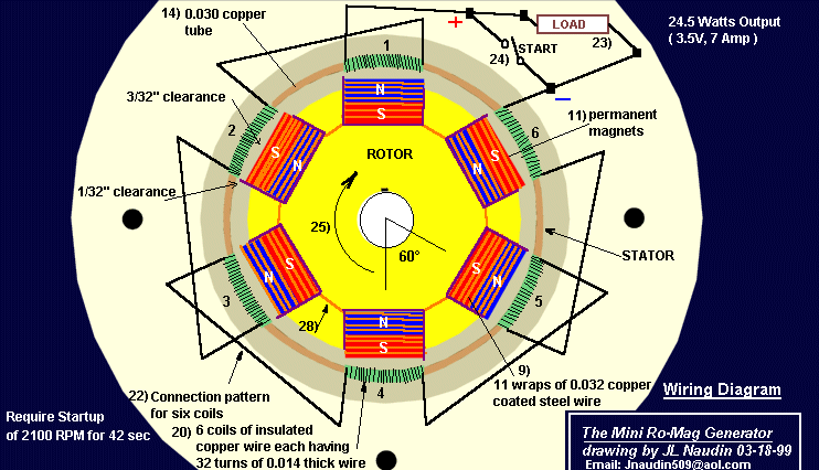
PARTS LIST AND CONSTRUCTION DETAILS
When building your first unit we suggest using the stated materials.
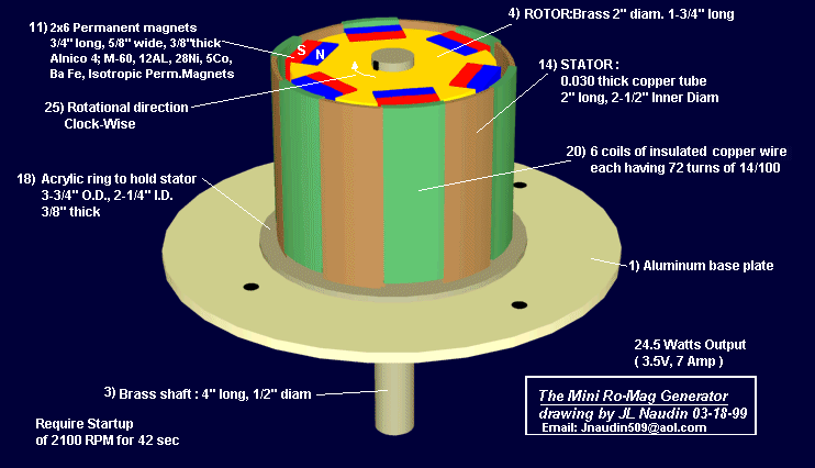
1) Aluminum Base Plate
2) Sleeve Bearing, 1" long, 1/2" inside diameter, oil impregnated brass.
3) 4" long by 1/2" diameter Brass Shaft
4) Brass 2" diameter Rotor, 1-3/4" long
5) Six rotor slots, each 1-3/4" long by .260 deep by 23/32" wide. These slots are spaced exactly 60 degrees apart.
6) One slot cut in center of Brass Rotor, 360 degrees around, 1/4" wide by
5/16" deep.
7) 12 slots (formed from the six slots as the 360 degree cut is made). Each slot is lined with .010 thick mica insulation.
8) A total of 228 pieces of U-shaped .040 thick copper coated steel wires. Each slot (Part #7) has 19 pieces of these wires fitted into the Mica, thus these wires do not contact the Brass rotor. The lead edge of these wires (See Figure 7) is flush with the Rotor's outer surface and the trail edge protrudes 1/8" above the Rotor's outer diameter.
9) Eleven complete turns of .032 thick copper coated steel wire. These 11 turns or 'wraps' accumulate to 3/8" wide and the same pattern is placed around all 12 magnets. When placed into the bent wires #8, they are a snug fit making firm contact.
10) Are 12 pieces of .005" thick mylar insulation inserted into the cores of the wires #9.
*11) 12 permanent magnets, insulated with the mylar, to not contact wires # 9. These magnets measure 3/4" long, 5/8" *wide, 3/8" thick and are made of a special composition and strength. Alnico 4, M-60; 12 AL, 28 Ni, 5 Co, bal Fe, Isotropic permanent magnet material cooled in magnetic field, Cast 9100 TS. 450 Brin, 2.2 Peak energy product. When inserted in the rotor the outer faces of these 12 magnets are not to be machined to a radius. The center of these magnets pass the center of the coils with 3/32" clearance. The edges, where the wires are wrapped, pass 1/32" away from the coils. This 'changing magnet spacing' aids in not only the release cycle but also contributes to rotational movement. (Sharp magnet edges which are facing the coils are to be sanded to a small smooth radius.)
12) Magnet polarity placement into Rotor. (See Figure 5.)
13) Connection pattern for wires wrapped around magnets. (See Figure 6.) The 12 wire wraps are divided into two sections, upper and lower of six each. There are no connections between these sections. The magnetic flow direction between the upper 6 wraps and the lower 6 wraps is attained by the 'flow direction' as shown in Figure 5. Viewing Figure 6 shows the wires wrapped around the magnet starting at the top 'north' half and then after 11 complete turns the wire exits at the lower 'south' half. As this wire then goes to the next magnet it arrives at an attract wire which is its 'north' side. Thus all wires get interconnected from south to north magnet half or north to south magnet half. The actual connections should be crimped copper clips not solder with insulation tubing to prevent contact to the Rotor body.
14) A .030 thick copper tube (stiff material) 2" long by 21/2" inside diameter.
15) Are six slots cut at the top of tube #14. These slots are 5/8" wide by
1/32" deep spaced at 60 degrees apart.
16) Are six slots cut at the bottom of tube #14. These slots are 5/8" wide by 5/16" deep and in line with the upper slots #15.
17) Six copper tube mounting points.
18) Acrylic ring to hold Part #14, measuring 3-3/4" O.D., 21/4" I.D., 3/8" thick bolted directly to Part #1. This ring has a .030 wide groove cut 1/4"deep to allow the six copper tube mounting points, Part #17, to be inserted.
19) A .002" thick plastic insulation paper to be placed around the inside and outside of Part #14.
20) Are six coils of insulated copper wire, each coil having 72 turns of .014 thick wire. Each coil is wound with two layers, the bottom layer to completely fill the 5/8" wide slot with 45 turns and the top layer to span 5/16" wide with 27 turns. To be sure each coil has the exact wire length or 72 turns, a sample length wire is wrapped then unwound to serve as a template for six lengths. A suggested coil winding method is to fill a small spool with one length then by holding the copper tube at the lower extension, then start at the plus wire in Figure 2 and temporarily secure this wire to the outer surface of the tube. Next, place the pre-measured spool of wire inside the tube, wrapping down and around the outside advancing clockwise until the 5/8" slot is filled with 45 turns. Then, return this wire back across the top of the coil for 15/32" and winding in the same direction again advance clock-wise placing the second layer spanned for 5/16" with 27 turns. This method should have the second layer perfectly centered above the first layer. After winding this coil, repeat the process by again filling the small spool with another length of pre-measured wire. A very important magnetic response happens as all six coils have their second layers spaced as disclosed.
21) This number identifies the top view of the second layer.
22) Connection pattern for six coils shown in Figure 2. When the unit is driven at start-up (hand crank) for 42 seconds at 2100 RPM, all six jumper wires must be together which means the plus wire goes to the minus wire connected by the start switch. After 42 seconds the load is added to the circuit and the start switch is opened. To double check your connections between the coils, note that the finish wire of coil #1 goes to the finish wire of coil #2, which is top layer to top layer. This pattern then has start of coil 2 (bottom layer) going to start of coil 3 (also bottom layer). When the copper tube with the coils is placed around the rotor, the distance from any magnet to any coil must be identical. If it measures different, acrylic holding shapes can be bolted to the aluminum base, protruding upward, and thus push the copper tube in the direction needed to maintain the spacing as stated.
23) Wires to load.
**24) Wires to start switch. **
25) Rotational direction which is clock-wise when viewing from top down.
26) Acrylic dome for protection against elements.
27) Coating of clear acrylic to solidify rotor. Do not use standard motor varnish. Pre-heat the rotor and then dip it into heated liquid acrylic. After removal from dip tank, hand rotate until the acrylic hardens, then balance rotor. For balancing procedure, either add brass weights or remove brass as needed by drilling small holes into rotor on its heavy side.
28) Insulation tubing on all connections.
29) Shaft for start purposes and speed testing (if desired).
This concludes the parts list for the Mini-Romag. Please share this information with others.
** **
Ok, done!
Source (preserved): Free information on free energy magnetic generator, no pollution, will recycle to save environment.html
The Mini-Romag Explanation
**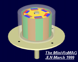
The Mini-Romag generator
Towards a possible explanation ?****
by Jean-Louis Naudin**
Created on 04-08-99 - JLN Labs - Last update 04-13-99
The Mini-Romag generator from *Magnetic Energy *is composed of two main parts : The Rotor and the Stator.
The Rotor is a brass cylinder with 6 pairs of magnets placed at 60° around its circumference. The magnets polarities are alternatively North and South.
The Stator is a copper cylinder with 6 flat coils wounded so as the coils axis are tangent to the rotation of the rotor. So, only the orthogonal component of the magnetic field of the magnets is used.
The oscilloscope pictures below, show the signal generated by a moving magnet :
The** ***left picture is the voltage generated across the coil when a magnet axis crosses the coil axis, this is a conventional setup for a magnetic generator.
The *right picture is the voltage generated across the coil when a magnet axis crosses the middle of the tangent coil (orthogonal component of the magnetic field), this is the case of the Mini-Romag generator.
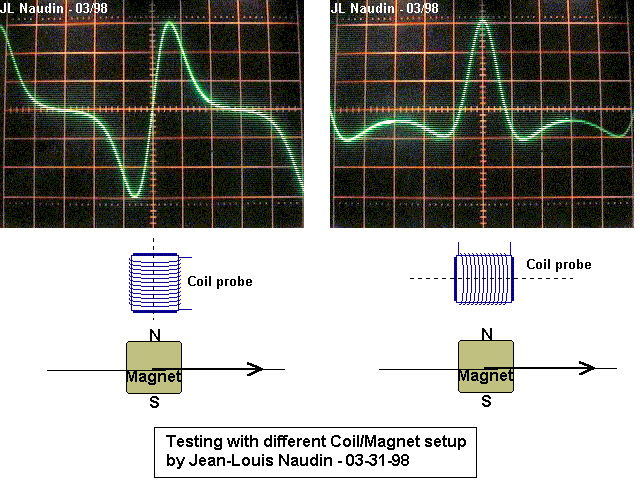
- In the left case (conventional generator), you can notice that the signal induced across the coil is symetrical Vs the zero line, the voltage value induced during the approach phase is equal to the voltage induced during the exit phase. During the approach phase of the North pole** of the magnet (from the left to the coil axis), a North pole is created on the bottom surface of the coil (according to the Lenz law), this creates the negative voltage shown. When the North pole of the magnet leaves the axis of the coil, a South pole is created on the bottom surface of the coil (according to the Lenz law), this creates the positive voltage shown in the scope picture. The flux in the coil has been reversed in this case. In this case there is always a magnetic coupling between the rotor (magnets) and the stator (coil).**
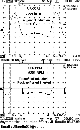
- In the right case (orthogonal field (Mini-Romag Setup)), you may notice that the voltage induced is more positive than negative (asymmetrical) when the magnet crosses the middle of the tangent coil. During the approach phase of the North pole** of the magnet (from the left to the middle of the coil), a North pole is created on the left surface of the coil (according to the Lenz law), this creates the negative voltage shown. During the exit phase of the North pole of the magnet (from the middle of the coil to the right), a South pole is created on the right surface of the coil (according to the Lenz law), this creates the negative voltage shown. The coil flux has never been reversed in this case. Now, look at the middle position (when the magnet crosses the middle of the coil). In this case, the orthogonal magnetic flux density drops to zero (this has been checked with a gauss meter). So the positive pulse induced in the coil is not due to the moving magnet, but it is generated by the collapse of the magnetic field (Back EMF)....In this case there is no magnetic coupling between the rotor (magnets) and the stator (coil) during the positive phase of the signal generated.**
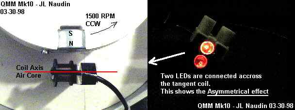
**This has been confirmed experimentaly. I have used a simple coil with an air core (no drag effect). A simple diode has been used to short the back EMF part, and you can notice that the rotor speed remains constant....
Another test has been conducted by connecting the coil to a power supply (up to 1.37A), I have noticed no significant change in the rotor speed.**
So, I have tried to explain only the half part of the Mini-Romag principle, the non-reciprocal effect when the device acts as a generator.
- Now, how is the device able to run itself as a motor/generator ?
As I have explained previously, there is no magnetic coupling** between the rotor (magnets) and the stator (coil) during the positive phase of the signal generated in the tangent coil and also that this positive part of the signal is produced by the collapse of the magnetic field. So, when the current reaches its maximum value the magnet is placed just in front of the middle of the coil. This is the case for all the coils/magnets (from 1 to 6). The wires have been connected so as all the Back EMF voltages are added (see the picture below).**
**At this moment, we have two important events : the Back EMF current is maximum and the creation of a magnetic field in the coil which contributes to ATTRACT the previous magnet placed at -60°. **
**For instance :
the coil #1 attracts the coil magnet #2,
the coil #2 attracts the coil magnet #3,
the coil #3 attracts the coil magnet #4,
the coil #4 attracts the coil magnet #5,
the coil #5 attracts the coil magnet #6,
the coil #6 attracts the coil magnet #1. **
According to this principle, it seems possible that the Mini-Romag is able to generate its own motional energy at a certain speed and thus, is able to run itself in self-sustained mode....
**The use of a copper tube for the stator contributes to increase the attraction of the previous rotor magnet, because the eddy currents induced change their magnetic axis direction due to the magnetic field interaction with the magnetic field generated in the stator coil. **
*This is a personal analysis, and this proposal needs to be checked experimentaly, so, today, I can't confirm that this device can work really as Magnetic Energy claims, but some premises encourage me to go further in this way...
*You will find below some additional informations sent by Magnetic Energy about the "Magnetic Current"...
***<<Very briefly, magnetic current is an energy that can flow through a wire, it can jump a gap and change form, it can be conducted through air and space, it can take on an infinite variety of polarities, it will not shock the body but make it numb depending on the intensity (more on this later), it flows when it is attracted to something, it can produce matter or break down matter in the right conditions, it can produce force fields, it can assist in momentum, it can assist in particle detection up close or far away, it can produce heat and cold in the right conditions, it can produce light in the right conditions, it can effect any natural system either enhancing it or alleviating it, it can enhance or detract from literally any energy form, it can be polarized into fields that can serve an infinite number of purposes, it does not deplete the earth's atmosphere like electricity, it occurs in various levels throughout nature, it can be monitored like electricity but it is not the same, nature does not produce electricity - it produces magnetic current that can be measured as electricity, magnetic current can move at a nearly infinite velocity, and it can be altered by the elements it interacts with - this is why the composition of the magnets is so very important - the composition or the elements determine the characteristics of the magnetic current as well as its speed and pulse rate. Every amazing or miraculous human event can be reproduced using magnetic current in the right conditions.>>**
Recommended documents**: **
- **"Magnetic Currents -- the Monopole ?" **by Kristen Joseph (Electric Spacecraft Journal July/Aug/sept 1991) Issue No.3
- **"New experiments about the Magnetic Current", **Ehrenhaft, Felix, Physical Review, Vol 65, 1944, pp 62-63
- **"Continuation of experiments with the Magnetic Current", **Ehrenhaft, Felix, Physical Review, Vol 65, 1944, pp 256
- "Magnetic Current" Radio News Electric World, April 1945, p22.
***From *******Jean-Louis Naudin : I shall be very interested and this will be very helpful for me, if you send me some additional informations about the "Magnetic Current" and some experiments that I can perform about this. Thanks for sharing your knowledge...
Any comments, ideas and suggestions are welcome.....
**You may see also : ******The Theory of Mini-Romag Generator** by Dave Squires**
 Email : ****JNaudin509@aol.com
Return to the** ******Mini-Romag** **page
** **
Ok, done!
Source (preserved): The Mini-Romag explanation .html
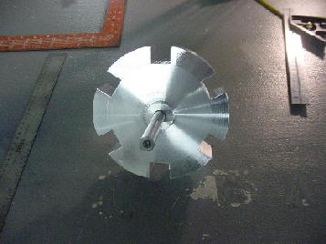
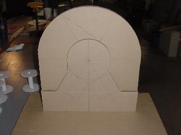
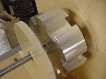
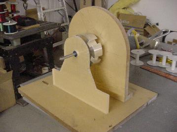
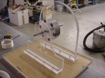
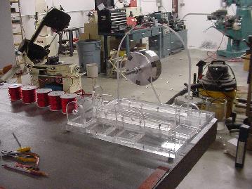
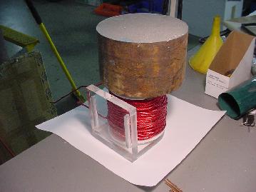
Bedini / Cole Window Motor — Notes

*The SG Project

I will be posting new pictures as the building process on the new energizer moves along.
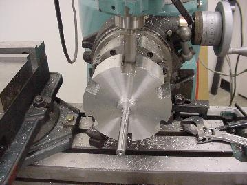
Machining the rotor
Finished Rotor 6' Diameter

Machining coil mounts
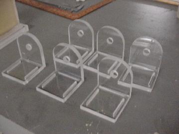
Finished Coil Mounts
Making the template for the bearings
Close up view after bearings are installed
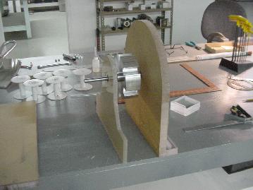
Side view alignment
Marking angle alignment of rotor
Rotor mounted with magnets and aligned
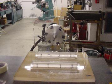
Front view of rotor with magnets
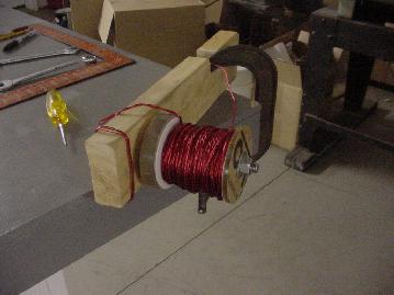
Winding the coils on the coil winding jig
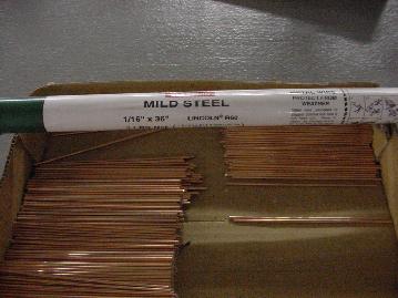
Cutting welding rod for coil cores
Coils wound and mounting bases finished
Coil being glued to mounting base under pressure
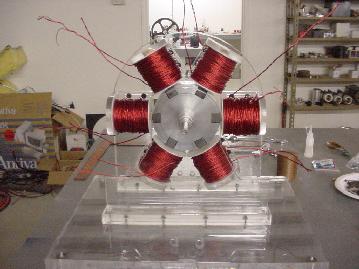
All six coils mounted on frame around rotor
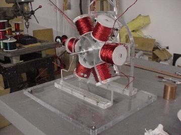
Angle view of finished mechanical set up
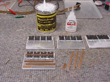
Mounting the switching circuits.
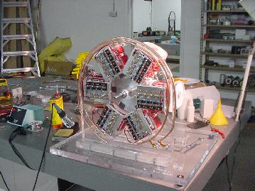
Soldering switching circuits to the coils, mounting buss bars.
** **
Ok, done!
Source (preserved): New Page 2.html
Preserved Source Pages (archived as-is)
These pages are kept verbatim as they were saved — the original markup, intact. Links open the preserved copy: